Difference between AC and A type RCDs
RCD is an international term and stands for Residual Current Device, which serves as a crucial safety device intended to safeguard individuals from potential fatal electric shocks when they come into contact with live elements like exposed wires. Additionally, it can offer a degree of protection against electrical fires, providing a level of personal safety that surpasses what conventional fuses and circuit-breakers can offer. There are two versions of protective current switches: RCCB, residual current circuit breaker and RCBO, residual current circuit breaker with overcurrent protection. In this blog, we will talk about the RCCB version, i.e. the one without overcurrent protection.
As the RCDs offer a high degree of protection against electric shock, these devices are indispensable in residential and commercial premises, and very often they are mandatory, for example in bathrooms, fire-hazardous buildings... Let us take a look at different types of RCCBs and explain the difference between type AC and type A, as well as also touch on type B, which will increasingly be used in the future.
Operation of RCD - AC type example
All users of electrical devices know that careless and incorrect handling of electrical installations and devices can be the cause of fire and other damage, personal injury and even fatality. The use of an RCD significantly reduces the number of fatal accidents due to electric shock, and also reduces the number of fires, caused by poor insulation of electrical cables. Thus, the RCD, in addition to the possibility of switch manipulation (switching on or off), is used for protection in the event of a malfunction, as additional protection and also protection against fire.
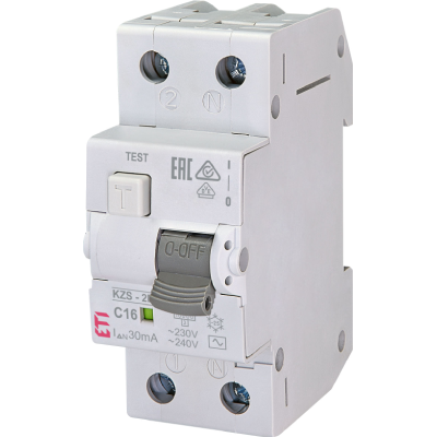
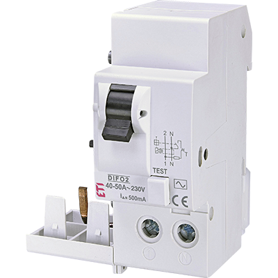
In Figure 1 we see a two-pole RCD of the AC type. How do we know it's type AC?
Figure 1: Two-pole RCD (EFI 2P) (63 A / IDn=100 mA)
That it is type AC can be seen by the mark on the top right in the rectangle, which is also shown in Figure 2.
Figure 2: indication on the RCD that it is an AC type
The next two important data on the RCD are the rated current (in Figure 1 it is 63 A), and the values are standardized for currents from 10 to 125 A. This is the current that the main contacts can withstand. The next important piece of information is the rated residual current (IDn). In practice, RCDs with the following rated residual currents are mostly used: 10mA, 30mA, 100mA, 300mA and 500 mA (0.5 A).
If we look at Figure 3 and imagine that we have the AC type RCD from Figure 1, let's try to explain the operation of the switch. Let's imagine that the resistance R is initially very high and we start reducing it. The current measured by the A-meter increases from a value of 10mA, 20mA..., but when it reaches somewhere between 50mA and 100mA, the switch turns off. We see that the current flows along the phase conductor (L) past the RCD and then along the neutral conductor (N) through the RCD. If the current flowed through the phase conductor through the RCD and back through the neutral, there would be no tripping.
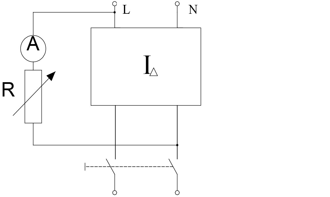
Figure 4: four-pole RCD in the TT power supply system (principle of operation - fault current flow)
Since the RCD serves as protection against electric shock by automatically disconnecting the power supply in electrical installations, let's try to explain it even better. The RCD is always activated at a current that occurs in the event of a certain fault. Thus, in the TT power supply system (Figure 4), in the event of a fault in an individual device or consumer (for example, a live conductor comes into contact with the housing of the stove, which could be very dangerous for the user). The fault current flows through the stove housing through the protective conductor (PE conductor), further through the protective grounding (Ra), which is at the building, then through the ground to the operational grounding (Ro) of the transformer station, then through the low-voltage winding of the transformer and through the phase conductor (via the low-voltage network and the low-voltage installation itself) to the consumer. This represents the electrical circuit of our fault current. All metal casings of electrical devices are grounded with a protective conductor, where the insulation is yellow-green in color. In the RCD, an asymmetry of the electric current occurs, since the sum of the incoming currents is not the same as the outgoing currents, and the RCD switch turns off in less than 30 ms, which is very important for people's safety. The difference in currents is known as residual current. If the residual current exceeds the value required to trip the tripping mechanism of the RCD, the RCD will trip the circuit. Figure 4 shows a four-pole RCD (40 A/0.3), or with a residual current (IDn) of 0.3 A. In this case, the RCD switch will trip between 0.15 A and 0.3 A. Since the fault current is significantly greater, the shutdown is immediate.
Now let's return to RCD types. The AC type is sensitive to alternating residual current, i.e. where fault currents are expected to be sinusoidal (Figure 2). The AC type RCD actually trips between 50 and 100% of the rated residual current, as manufacturers use standardised permissible limits.
RCD type A
Figure 6: Type A RCD (16A/300mA)
Figure 7: Symbol of type A, RCD
What is the difference between type A and type AC?
A type, in addition to alternating current, is also sensitive to half-wave or full-wave directional alternating current (pulsating direct current). An example are rooms with an increased risk, such as the bathroom, where an RCD with a rated differential current of 0.03 A (30 mA) is mandatory, as consumers such as fans are used there, which have half-wave rectification with a diode for a certain function. A type of RCD trips between 35 and 140% of the rated residual current. So for an RCD with a residual current of 30 mA it trips between 10.5 mA and 42 mA. Manufacturers use standardised tolerances.
Figure 8 shows a type B RCD, which is even rarer in electrical installations. Due to the extraordinary increase in various electronic devices with rectifiers, an increase in the use of this type of RCD can be expected.
Figure 8: four-pole RCD type B (16A/30mA)
The B type RCD can be recognized by the symbols in those three rectangles above in Figure 8. The B type, in addition to alternating and pulsating direct current, also works with smooth direct residual current and also with high-frequency currents. It is used in facilities where we have e.g. three-phase rectifiers, frequency converters and other electronic devices. The B type of RCD, on the other hand, trips between 50 and 200% of the nominal residual current.
You can find more details regarding the RCDs in our manual.
And here is a cheatsheet on various types of RCDs and applications they are used in.


